Knowledge Hub & Insights
Knowledge Hub & Insights
Welding productivity depends on more than arc stability and operator skill. Heat control matters when torches, guns, lasers, or high-duty-cycle systems run for extended shifts. The International Energy Agency reports that industry remains one of the world’s largest energy-consuming sectors, making equipment efficiency an important purchasing factor. Cooling systems may use less power than major production machines, but inefficient pumps and restricted airflow can still increase operating costs.
This guide examines seven leading options for an Industrial Water Cooling Unit for Welders. Each model is assessed through practical criteria, including cooling capacity, flow rate, temperature control, pump reliability, noise, service access, and compatibility with welding equipment. ISO 5171 and IEC 60974-2 provide useful technical references for welding equipment and liquid-cooling systems. The U.S. Department of Energy also emphasizes motor, pump, and heat-transfer efficiency in industrial energy management guidance. Those principles matter on the factory floor, where a clogged filter, warm return line, or undersized reservoir can quickly affect performance.
Real workshops are rarely perfect. Ambient heat changes. Hoses age. Operators sometimes ignore alarms. Therefore, no shortlist fits every fabrication environment. A compact unit may suit a repair bay, while a higher-capacity chiller may be safer for robotic welding or continuous production. We compare published specifications with practical operating concerns, while recognizing that manufacturer data does not always reflect field conditions. The final choice should match the welder’s duty cycle, coolant requirements, maintenance resources, and local electrical supply. Reliability comes from that match. Not from a headline rating alone.
For welders, a water cooling unit is not chosen by voltage alone. Flow rate, heat load, ΔT, and coolant range control torch stability. ASHRAE Handbook—Fundamentals lists water’s specific heat near 4.18 kJ/kg·K at ordinary temperatures. This supports a practical equation: cooling capacity equals mass flow × 4.18 × ΔT. Keep it measurable.
Measure the torch circuit’s heat load, not only the welder’s electrical rating. A 3 kW heat load with a 5°C temperature rise requires approximately 8.6 L/min of water flow. Add a reasonable design margin for hose losses, dirty filters, and warmer workshops. Flow below the cooling circuit’s minimum can create hot spots. A display may still look normal.
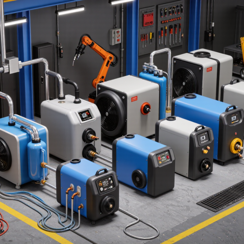
The seven useful unit categories include compact recirculating coolers, air-cooled chillers, heat-exchanger systems, high-flow weld coolers, dual-circuit units, low-temperature units, and modular skid systems. Coolant range matters. Water handles heat efficiently, while glycol mixtures improve freeze protection but usually increase viscosity and reduce heat capacity. The U.S. Department of Energy’s industrial assessment guidance supports measuring operating conditions before selecting equipment. My own sizing mistake would be trusting nameplate power too much; actual duty cycles, blocked airflow, and short hoses can change the result quickly. Test under real welding conditions.
Typical engineering configurations for selecting a water-cooling unit for TIG torches, MIG guns, plasma systems, resistance welding equipment, and high-duty-cycle welding applications.
| Unit Configuration | Typical Welding Application | Recommended Coolant Flow | Design Heat Load | Design ΔT | Typical Coolant Operating Range | Reservoir Size | Recommended Heat-Exchanger Capacity | Selection Notes |
|---|---|---|---|---|---|---|---|---|
| 1. Compact TIG Cooler | Air-cooled TIG torches and light-duty GTAW equipment | 2 L/min | 0.5 kW | 4 °C | 15–30 °C | 2–3 L | ≥0.75 kW | Suitable for short weld cycles and torch loads below approximately 150 A. |
| 2. Standard TIG Cooler | Water-cooled TIG torches used for stainless steel and aluminum welding | 3 L/min | 1.0 kW | 5 °C | 15–30 °C | 3–5 L | ≥1.25 kW | A practical general-purpose range for medium-duty TIG welding. |
| 3. High-Flow TIG/MIG Cooler | High-amperage TIG torches and water-cooled MIG guns | 4 L/min | 1.5 kW | 5.4 °C | 15–30 °C | 5–7 L | ≥2.0 kW | Provides additional flow margin for long torch leads and high-duty-cycle work. |
| 4. Industrial MIG/MAG Cooler | Robotic or production MIG/MAG welding with continuously water-cooled guns | 5 L/min | 2.5 kW | 7.2 °C | 15–32 °C | 7–10 L | ≥3.0 kW | Use a larger reservoir and adequate pump head when hoses are long or restrictive. |
| 5. Heavy-Duty Multi-Torch Cooler | Two or more welding torches, automated cells, or demanding production lines | 8 L/min | 4.0 kW | 7.2 °C | 15–32 °C | 10–15 L | ≥5.0 kW | Choose independent flow monitoring when multiple torches share one cooling loop. |
| 6. Plasma and High-Current Welding Cooler | Plasma torches, submerged-arc accessories, and high-current welding heads | 10 L/min | 6.0 kW | 8.6 °C | 15–35 °C | 15–25 L | ≥7.5 kW | Verify torch manufacturer requirements for minimum flow, pressure, and coolant conductivity. |
| 7. Process-Grade Recirculating Chiller | High-duty-cycle robotic welding, resistance welding tooling, and multiple heat sources | 15 L/min | 10.0 kW | 9.6 °C | 15–35 °C | 25–50 L | ≥12.0 kW | Best for continuous operation where stable coolant temperature and alarm integration are required. |
Select a unit that matches the actual thermal load and duty cycle. A 10 kW load may need about 29 liters per minute at a 5°C rise. A 30 kW load may need about 86 liters per minute. Add a realistic 15–25% design margin when conditions vary. Do not guess.
Stable temperature protects torches, cables, and process consistency. Temperature drift can appear during long welding cycles. TIG and laser systems may react to small thermal changes. A digital sensor helps operators notice drift early. Small changes matter.
Check cooling capacity, flow rate, pump pressure, and reservoir volume. Review minimum flow requirements carefully. Inspect alarm functions, filter access, and control accuracy. A compact unit may fit the floor but struggle under continuous work. That risk is easy to miss.
Yes, their cooling demands can differ significantly. TIG systems commonly need clean, steady flow for torch protection. MIG systems may require stronger heat removal during long production runs. Robotic cells need dependable circulation across repeated cycles. Laser systems often need precise temperature control and low vibration.
No. Oversized pumps can waste energy and stress fittings. A larger chiller may use more standby power. However, extra capacity can protect equipment during extended cycles. The best choice balances head pressure, flow, load, and operating cost. More is not always better.
Include radiant heat, hose losses, fouling, and intermittent welding cycles. Dust and welding fumes can also affect heat exchanger performance. Workshop temperatures may differ from test conditions. My initial sizing estimate is often too optimistic. Recheck the assumptions.
Inspect hoses for discoloration, mineral deposits, and visible wear. Clean the heat exchanger on a defined schedule. Keep filters accessible for quick inspection and replacement. Poor water quality may restrict flow within weeks. I underestimated that once.
Leave clear space around the unit for airflow and repairs. Confirm communication signals and alarm compatibility with the control cabinet. Protect hoses from sharp bends and excessive tension. Check the unit during a full welding cycle, not only at startup. Crowded installations become difficult to trust.
Selecting the right Industrial Water Cooling Unit for Welders begins with understanding the process heat load, required flow rate, temperature difference (ΔT), and acceptable coolant range. This guide evaluates seven unit types by cooling capacity in kW, circulation performance in L/min, and coefficient of performance (COP). It compares high-capacity chillers designed for industrial heat loads from 10 to 30 kW with precision systems suited to TIG, MIG, robotic, and laser welding equipment. The goal is to match cooling performance with duty cycle, torch requirements, and operating conditions.
The review also explains how stable coolant temperatures can improve equipment reliability, weld consistency, and energy management. Safety and efficiency considerations are assessed using the practical principles of ISO 5149 and ASHRAE 90.1, including ventilation, refrigerant safety, electrical protection, insulation, and efficient component operation. By balancing thermal capacity, flow control, maintenance needs, and energy consumption, users can identify a dependable cooling solution for demanding welding environments without oversizing the system.